In the beginning Uniform: Difference between revisions
Jump to navigation
Jump to search
No edit summary |
No edit summary |
||
| Line 13: | Line 13: | ||
{| border="1" cellpadding="5" cellspacing="5" | {| border="1" cellpadding="5" cellspacing="5" | ||
|- valign="top" | |- valign="top" | ||
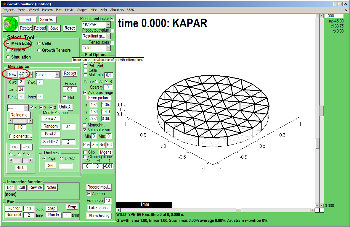
|width="300px"|Create a canvas by clicking on ''Panel Mesh Editor:new''. A variety of preset shapes are available, here we choose a Circle with 4 concentric rings of nodes that is 2 mm in diameter.<br><small>Idea: Special shapes can be imported as ''OBJ'' files. ''</small> | |width="300px"|Create a canvas by clicking on ''Panel Mesh Editor:new''. A variety of preset shapes are available, here we choose a Circle with 4 concentric rings of nodes that is 2 mm in diameter.<br><br>By default the mesh is autoscaled and autocentred - it makes it easier to see shape changes but to see growth these are best turned off. Set the Panel:Plot options:Auto axis range to unticked and insert plot ranges -2.5 to 2.5 on x and y axes and 0 0 on z. Also turn off Menu:Plot:Autozoom and centre.<br><br><small>Idea: Special shapes can be imported as ''OBJ'' files. ''</small> | ||
|width="500px"|[[File:gftboxGUIB_2.jpg|500px|GFtbox interface]] | |width="500px"|[[File:gftboxGUIB_2.jpg|500px|GFtbox interface]] | ||
|} | |} | ||
Revision as of 20:43, 27 May 2011
Back to Tutorial pages
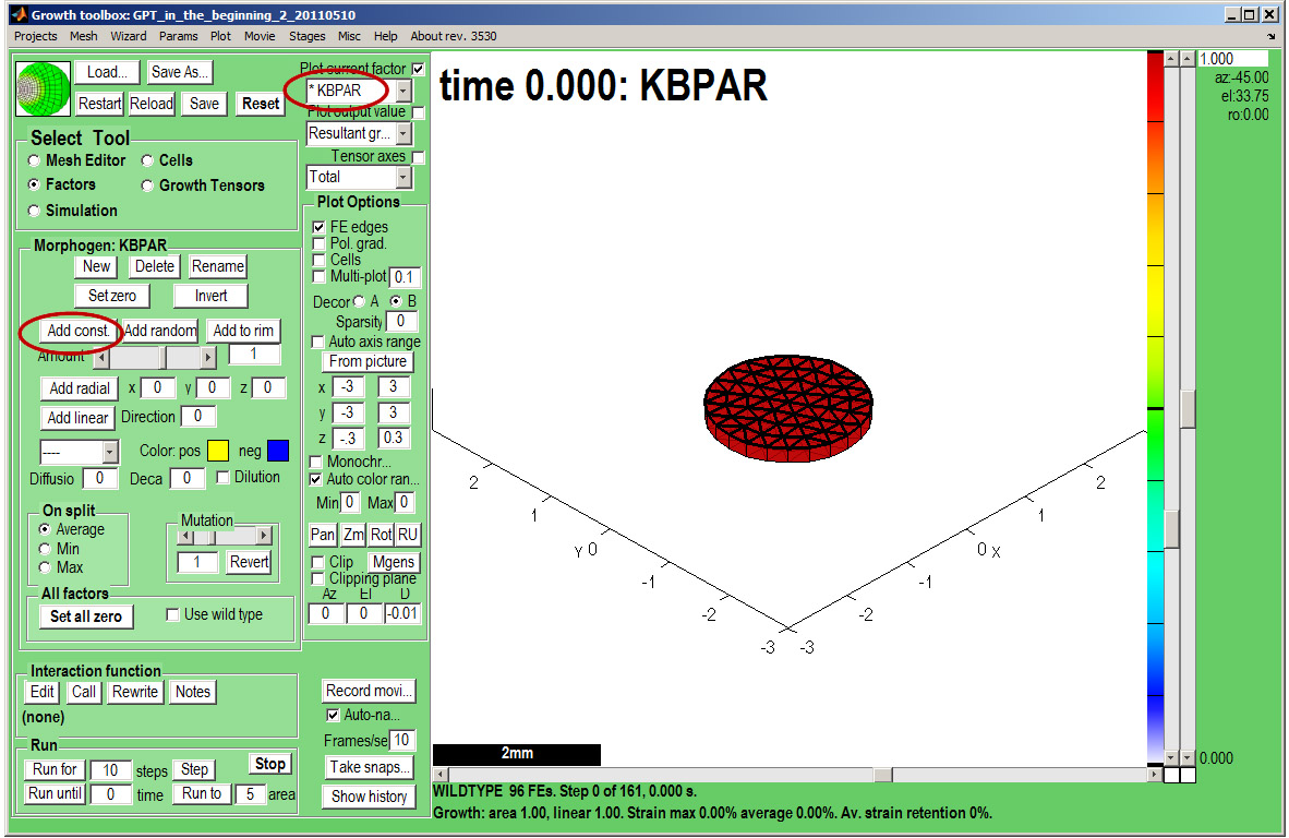
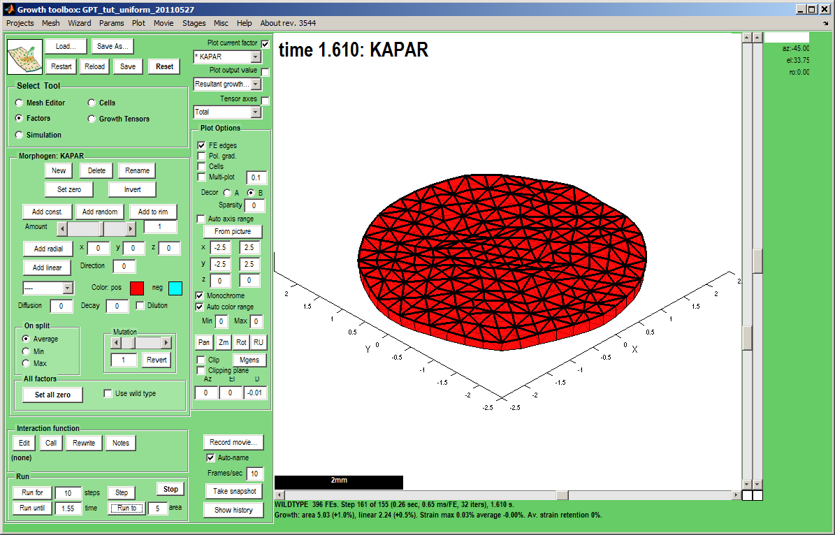
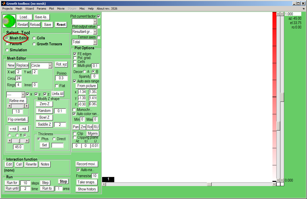
We start with a number of very large screenshots (don't be daunted they are just here to orient you). They show the GFtbox graphical interface.
Modelling uniform growth using the GUI alone
First view
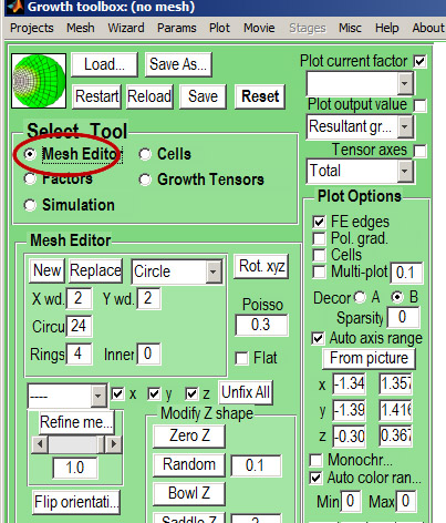
| The GFtbox user interface. Focus on the Select Tool Panel. Here the Mesh Editor has been selected and the Mesh Editor panel is visible.
|
|
